
A beefy electronic load (#P4)
This is a ranty introduction to the electronic load project – photos, circuits and more will be available in part 2 next week!
So…I’ve been torturing power supplies (and to a lesser extend: batteries) for ages. Usually to check their health status by comparing the current peak performance to the claimed values in the datasheet. Once you see voltage rails dropping where they should not, it’s time for a replacement of the unit, or in case of specialized PSUs, for a swap of the electrolytic caps.
But the crudity of my testing always bothered me – hooking up power resistors, measuring voltage and current, manually connecting and disconnecting the DUT, never hitting exact performance figures because of the limited selection of torture devices I had around. Sure, the 500g “swept together from the warehouse floor” power resistor packs from Pollin are in fact a bargain, but it’s 2017 and I’m still piecing together thick resistive wire covered in cement? Nah, that has got to stop.
Before starting working full-time, I had a few months with a lot more leisure time than usual. I starting building a modified version of MJLortons electronic load, which itself is based on some teeny-tiny circuit from Dave Jones, back from EEVblog #102 (have a look at Martin’s forum for more details). Dave was using a MTP3055V n-channel MOSFET, which (I have to say), isn’t exactly the most beefy part on the planet with 12A, 50V, RDSon of 150mΩ specs in a TO-220 case. The MOSFET is rated at 48W dissipation at the usual unrealistic ambient conditions, which Dave corrected to around 11 watts in his application with the rather small heat sink. 11 watts will do for an oldschool-chemistry battery, but not for me! ![]()
The version from Martin Lorton uses a more powerful BUZ31L H MOSFET, which still is in TO-220 format, but offers 200V of drain-source voltage (not sure about isolation distances for TO-220…), 13.5A, but 200mΩ of RDSon. He’s also pairing this with an 1Ω, 50W power resistor, which, in some cases, takes off quite some load from the MOSFET and allows for high total power dissipation in low-voltage test scenarios.
Thing is: The BUZ31L H is an obsolete part and also was hard to get in Germany before that. And I’m not a big fan of TO-220 in power applications – because there is TO-247 for that! 15x20mm² compared to 10x15mm² (including the tab) allows for a hell of a ride…
So after a small test with an IRFP240 (with relatively high RDSon of 180mΩ – close to those of Dave and Martin), I finally decided to go with the IRFP250N. Given their performance figures of 200V, 30A, 75mΩ RDSon and 214W max dissipation at the same fictional 25°C Tcase, they are dirt cheap at 1€ per unit, for example at Reichelt. If you decide to use that MOSFET type as well, be sure to take the 250N version, not the 250 – it not only has 85mΩ RDSon and slower switching time, but also costs 50% more. Guess that’s the part for folks that do not want their BOM list changed.
While the IRFP250N isn’t explicitly advertised as MOSFET for linear applications, it has “ease of paralleling” listed in the key features in the datasheet. Nobody right in their mind would ever do this, but it’s nice to know, isn’t it?
This is Martin’s circuit:
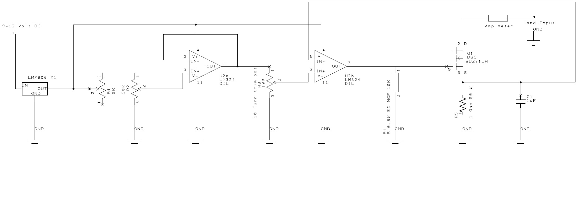
I used this as base for my own development: Get an op-amp, set some arbitrary voltage to the noninverting input by hooking up a voltage divider, couple back directly to make it a buffer, and then run the second op amp in the very same case with that voltage (divided again by a trim pot – depending on your power resistor). The loopback path will be the voltage between the MOSFET and the source resistor. Adjusting the MOSFET voltage will result in a different effective RDS (we’re running in linear regime here!), effectively changing the voltage divider column consisting of the MOSFET and the fixed power resistor (and the amp meter shunt, if you’re using one). So the built-in magic in the op-amp will find the operating point of the MOSFET according to your ten turn pot in the first voltage divider.
That’s simple, elegant, and it works nicely – I’ll show you the first PCB and some performance insights next week.