
modellbaufuchs 26650 6S2P 4.6Ah LiFePO4 battery pack with balancer port (WHL #29)
And another one. I’ll churn these battery reviews out once per week now, even though I said I would rather go biweekly. It’s not much extra effort – charging, discharging and then plotting the data has to be done anyway, taking some extra photos and waffling on about it on my blog is a plus.
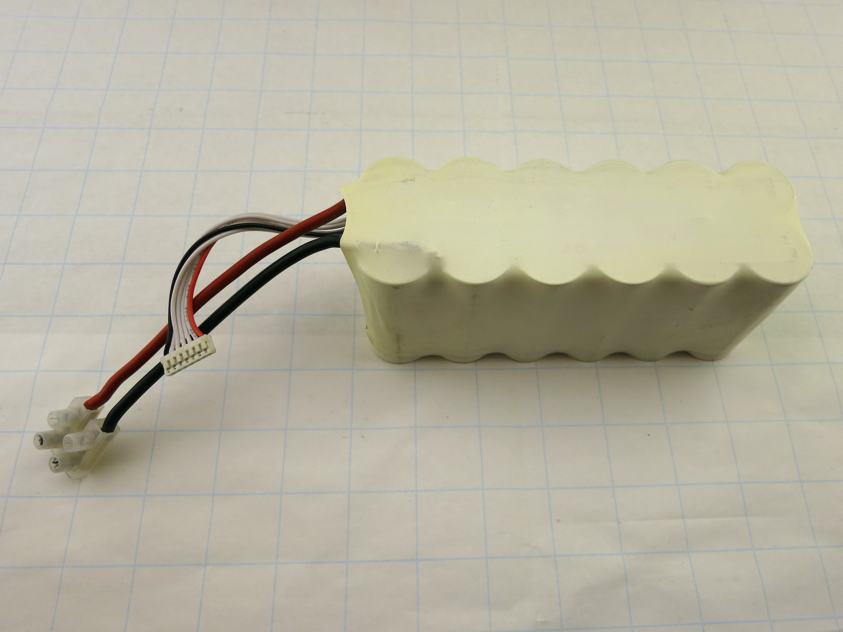
So this week’s item is a 6S2P battery pack, LiFePO4, rated at 4.6Ah. It’s from modellbaufuchs, which I just visited in preparation for this post. Not sure if they are still in business, as their latest news item on the page dates back to early 2015. I also couldn’t find the exact “Konion 266523” model in the shop; they only list 1P and 3P (some LiCoO, some LiFePO) 6S models now. As the 1P LiFePO models are just short of 100€ a pop, I’d guess this one was around 150€ to 200€ back in the days. Not cheap, man, not cheap.
The pack is pretty straight-forward on the outside, no marking on the shrink wrap, no nothing:

Same on the back:
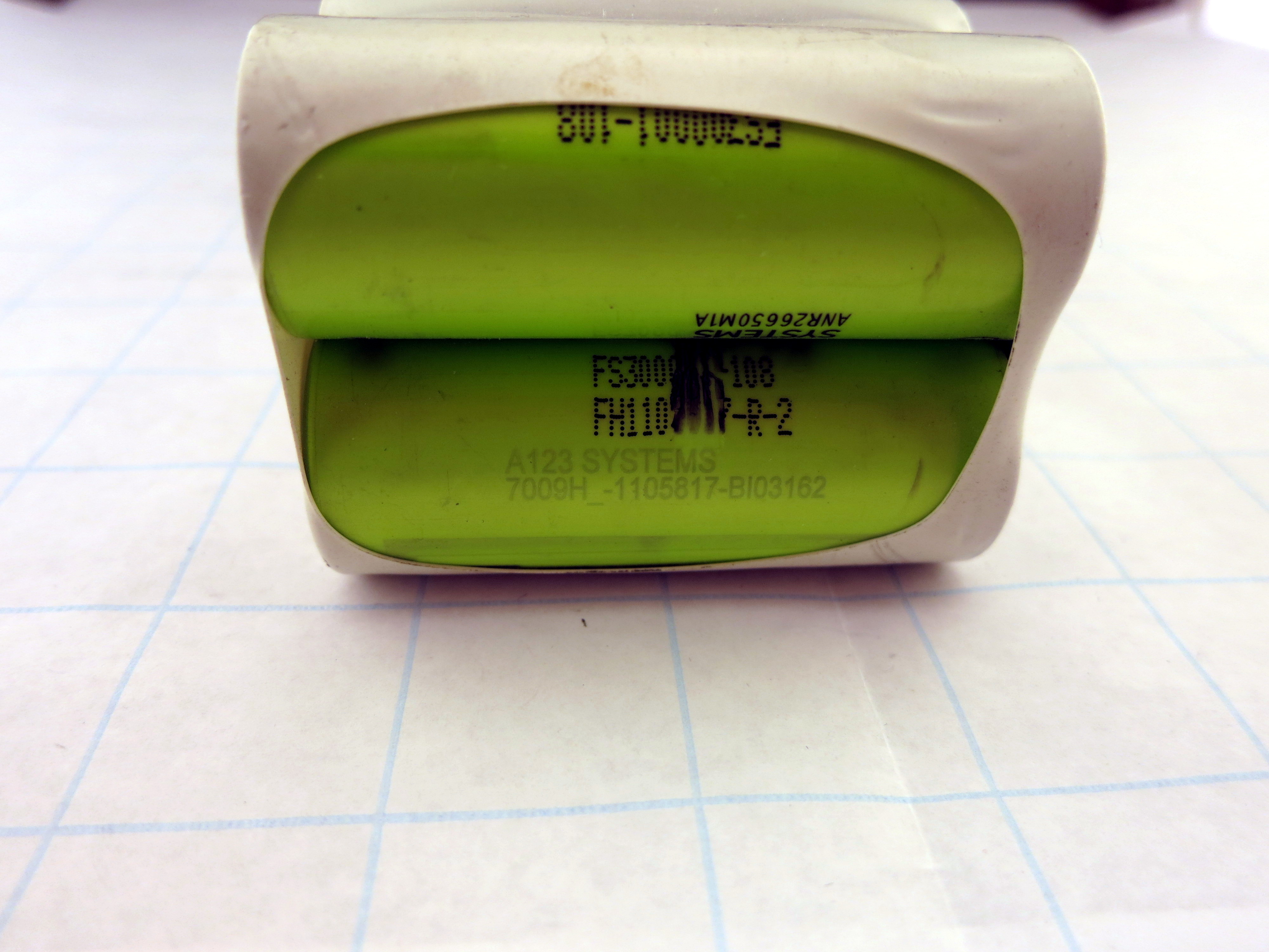
It does present some info on the end of the pack – it’s made from A123 batteries of the ANR26650M1A type. Yep, A123 went bust in 2012 and were sold to some Chinese company. Not sure if they continued building batteries as if nothing happened of if that is old stock. The other markings are 7009H_-1105817-BI03162 – again not sure if there’s a date code in it, I doubt the 03162 is something in 2016 (that’s probably too recent). On the contrary, LiFePOs haven’t been around for a long time…
On the front of the pack, there’s the label of modellbaufuchs.de, stating a “Konion 266523” model (googling “Konion” yields loads of Sony cells – is that some generic RC battery pack term, or did Sony buy parts of A123?). Nominal 19.8V = 3.3V per cell, maximum charge voltage 21.6V = 3.60V per cell (the O’Cell ones were specified to 3.65V), nominal 4.6Ah capacity and 2C charging rate.

The 4.6Ah is interesting, as the cells are labelled “FS30001-108”, indicating 3.0 Ah – much closer to the two batteries from the last blog posts. 4.6Ah is a much lower rating than the 2P = 6Ah configuration that is used – is that a RC battery thing maybe? After all, the pack has some beefy 6mm² wires coming out of the front, furthermore, a balancer port is provided. The other batteries in the shop are specified to 25-30C in 1S configuration…

Although my electronic load does take some watts for a short amount of time, fully discharging a 20V battery pack with several amp hours at currents worthy of 6mm² is beyond the capabilities. I did full runs at 2A, 4A and 8A, meaning 0.4C, 0.8C, 1.7C – that’s kindergarten for this pack. It does, however, get notably warm in the highest setting, around 15 to 20 °C above ambient (35 to 40°C in total), but the MOSFETs are a bit more stressed at around 100°C Tcase ![]()
First result, which also applies to the most recent LiFePO tests: Capacity vs. discharge cut-off. I had the A123 26650 spec embedded into a previous post, here it is once again for reference:
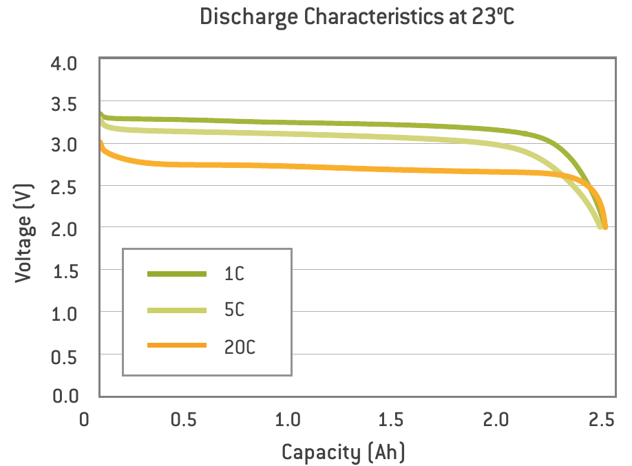
So A123 allows for discharging down to 2.0V under load. Not a big fan of that, and comparing 2.8V, 2.7V and 2.6V cutoffs (same measurement, just reading the data points), I don’t see the point in going any lower:

Sure, that might be different for your 20C heli discharge cycles, but at lousy 40 watts, 3955, 3993 and 4017 mAh (sorry for the overly precise readings) make no difference at all. I’d not stress the chemistry that much more to squeeze out a shitty 1.5% additional energy…
As you can see, the voltage drops much steeper than in the A123 example. And it’s doing that around the 4Ah mark, meaning these cells are 2.3Ah type or they are pretty worn already. I know they were in use for tests, but nothing close to RC heli usage – 20 watts constant power draw until dead, maybe.
So how does 2A – 4A – 8A compare?

Not too bad, I guess – yet for less than 2C tested and 20C+ allowed current, that wouldn’t end well in heavy discharge cycles. Funnily, the intermediate 4A test does score almost worse than both the light 2A and the heavy 8A cycle, just like in the A123 graph. Voltage drop towards the end also isn’t that steep for the heavy cycle, that’s impressive. And, if you think back of the first Wan Hung Lo battery pack, the 2A cycle is repeatable without notable deviations beyond measurement uncertainties (or even killing individual cells) – A123 certainly delivered quality ![]()
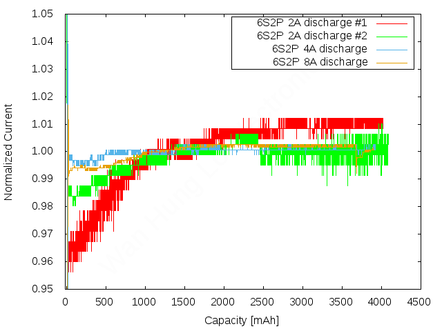
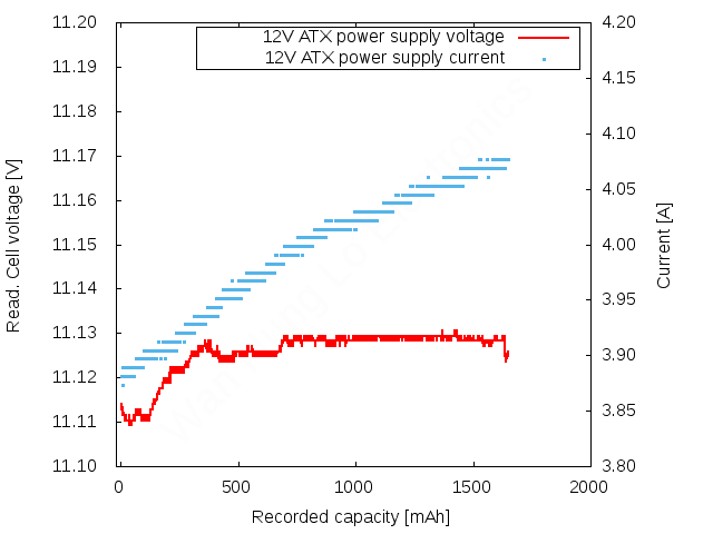
Last thing to discuss for today: The climbing current thing that I mentioned in the O’Cell post. This didn’t happen when the system wasn’t under any load, like when I was measuring voltage stability with the voltage reference. It needs some power to induce the effect – and I think the RDSon measurement to get a current reading plays a major role in it.
Here’s the current readings of above tests:

Looks nicer when you plot it in relative units:
I have say a thing or two about running these tests: The first 2A test was done by just hooking up everything and starting the discharge. The electronic load was at room temperature and heated up. Not much (40 watts), but a little bit. The power gating MOSFET (IRFP4668) even less, as it only represents 10mΩ of the entire resistance. Say we’re at 20V and 2A, that’s an effective circuit resistance of 10Ω. So the MOSFET has 0.1% of total resistance, therefore 0.1% of the entire voltage drop according to Kirchhoff, and therefore 0.1% of the wattage – 40mW. That’s not much for a TO-247 case that offers around 0.3 K/W of thermal resistance for junction to case and the same for case to sink – heatsinking is done on an aluminium part of the case. Junction to ambient thermal resistance (“free standing”) is 40 K/W, but that’s not adding much. But: It is close to the first heat sink of the load MOSFETs, which are also mounted somewhere on the same aluminium case. The IRFP4668 not only gets its fair share of IR radiation, but also slowly heats up through the case heat “sink”. It’s a sink for everything else, too bad he’s not contributing as well…might have to insulate instead of sink this transistor. Who would have thought ![]()
So for the other tests, I did some pre-heating with the ATX power supply at around the same total power (higher current due to lower voltage level – 12V). It takes some time to heat up everything – but then, due to the massive Fischer heat sinks with 1.3K/W each (leave alone forced air cooling), the cooldown is rapid. So that worked for the second 2A run and even better for the 4A one, but I was too slow at the 8A run.
At 8 amps, I did a crude measurement at the gating MOSFET, telling me that temperature was around 2K above ambient. Luckily, we have a datasheet for the IRFP4668 RDSon characteristics under temperature variation:
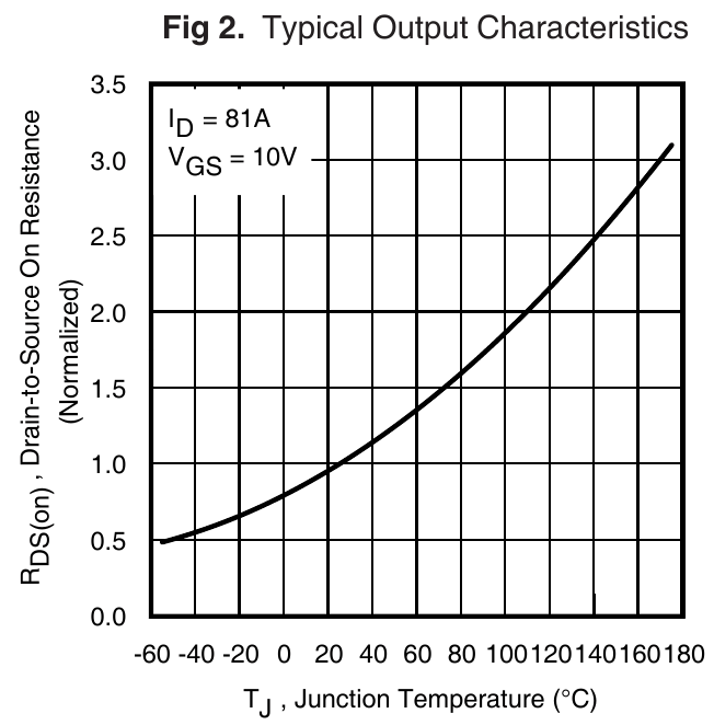
It doesn’t tell us exact coefficients, but doing some rough readings and centering around the 100% @ 23°C (296K) mark, we can fit an exponential curve to it – R(T) = R(296K) * Exp ((( T / 296K ) – 1 ) * C) (note the need for absolute temperatures here – good luck to my friends, the Fahrenheit yankees). Our temp coefficient C is about 2.2 as can be easily determined by playing around a bit in your spreadsheet file. No need for exact values!
What does at 2K rise mean for our RDSon with that model? Glad you asked. R(25°C) = R(23°C) * 1.015 – a 1.5% increase in resistance, which screws over the fixed voltage drop -> current conversion factor set to the ADC routine. 3K would result in a 2.3% rise, 1K in 0.7% (roughly linear for such small variations). See something in that ballpark in above graphs? Or in the regulated DC source measurement from last blog post?
Yep, that one plays a major role in our apparent current deviation over time. The current is stable as verified by my multimeters in both direct measurement as well as for the long-term clamp readings. I said it before and I’ll say it again: Using the RDSon of that power gating MOSFET is not a good idea – it works in principle, but it’s not stable for higher loads. If you just use the electronic load for several watts of total power dissipation and the MOSFET faces some milliwatts, you may be fine. But having several thousands of ppm (linearized around the operating point!) of current reading temp-co and then raising the case temperature by a few degrees is a terrible plan.
Next post: Another battery ![]()
Next shopping item: A sub-100ppm shunt resistor ![]()
Cheers!