
Convenient IBM x3650 server PSU power distribution board (#P35)
On the occasion of selling the second PSU from the long dismantled IBM x3650M1 machine (part of the stack shown in #P23), a direct result of eBay getting greedy and increasing their commission from 10% of the item price to 11% including postage (WTF?) plus 35 cents per item, I need to publish this real quick. I still do have access to powerful 12V supplies that can operate my lightbox setup to take photos of the things are usually operating the lightbox, but it would be pretty inconvenient to do so ![]()
So here’s another piece of Open Hardware – a custom PSU board for said IBM power supply. It’s an Artesyn brand model, 7001138-Y000 Rev H, FRU P/N 7001138-Y002, IBM P/N 24R2730 and IBM FRU P/N 24R3731 (geez, isn’t one or two of these enough for unique identification?). 100-240V wide input, 50/60 Hz, 12.1V output at 69 amps and some aux power 5.0V at 0.2A. Kicker with most server PSUs, independent of 1U/2U/3U sizing, is that they do not connect directly to the components via the standard 20+4pin ATX, 4/8pin ATX12V-EPS12V, 6/8pin PCIe and SATA and Molex-y style connectors. Instead an intermediate PSU is used that watches the two (sometimes three) PSU slots and decides where to draw power from. These boards are proprietary and often custom to their very system, e.g. a x3650M2 or x3660M1 would use a different one. They range from a somewhat simple switch to achieve basic PSU redundancy to units that generate voltages other than 12V, do load balancing (doesn’t have to be evenly distributed all the time) and report power usage and health information via SMBus which is related to I²C. While that’s all fine and dandy, it does limit the versatility of these units once retired, which is the case for this 13 year old x3650M1 machine here.


And this is where my PCB comes into play. You see, those PSUs will not start right away, but instead they will wait for some signal before any usable voltage is present. Fortunately in this case it’s not a digital signal (as those PSUs can be talked to with SMBus as well) but a simple contact that needs to be grounded, similar to the PS_ON pin on a regular ATX power supply. There is something more advanced going on for voltage adjustment and over current protection (high peak loads on power-up), but to get going and draw some 200+ watts, bridging a certain contact is sufficient.

Kicad/Gerber files are linked on the bottom of the page. I’ve ordered this PCB via JLCPCB for 15.10€ (5 pcs) plus 4.78 shipping, so 19.88€ total / 3.98 per PCB. Reason for this is the ENIG finish that is not perfect for daily mating cycles, but I just couldn’t justify spending 3-10x the amount for a proper hard gold finish on the contacts like the original PCB has. OSH Park, usually the go-to manufacturer for gold plated boards, is actually more expensive and also “only” does ENIG, no hard gold coating. They make three boards instead of five, but oh well, I only need one to work and I gave away a second one with the sold PSU.
So here’s the original board that had some pretty high-current connectors present before I removed it from the rest of the intermediate PSU….

The two shorted pins that make the PSU fire up right away are better visible here. It’s a complicated arrangement of tracks on that double sided PCB, they didn’t really optimize either PSU output pinout or intermediate PSU input pinout for that. Board identifier is 5107135-0F00 Rev A.

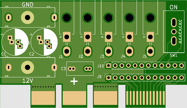
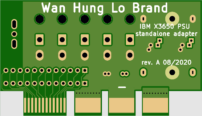
And here’s my PCB. Someone thought clearance would be enough, but it isn’t. The PCB actually doesn’t go all the way into the connector as it is stopped by two metal bits of the PSU. Dang.


If there was a second revision, I’d fix this in hardware – but the solution for me is just removal of the metal collar on the PSU, as the connector layout itself is perfectly alright. One also could cut into the aux tracks if the advanced stuff in the PSU never needs to be accessed, as probably is the case here. That would leave the PSU completely unmodified.

Now, the PCB itself offers enough connection options for me, obviously YMMV but that’s where the Open Hardware stuff is best at. I have placed five spots for 90° angled 2-pin Molex connectors and two (plus/minus) footprints for 4mm banana jack housings. There’s also some space for capacitors and the entire aux connectors of the PSU are accessible in 2.54mm dual-row format – not the original pinout, as that didn’t include some of the pins. Most importantly, there’s also a switch present so that the PSU output can be turned on/off at any time without disconnecting the mains.

The Molex connectors are of the MiniFit 5569 type, usually mating with 5557 housings. Apparently there is a version available that can be fixed in place with a screw from underneath, hence the hole in the PCB – mine from China (1.26€ for five pairs plus shipping) do not have that, but they aren’t that stressed or accessed that often, so it’s fine. The original parts are specced for 13A per contact. Unfortunately the angled and straight headers use a different pin spacing (I only realized that today), so one should make a unified footprint in Kicad to offer some flexibility.
The banana jack footprints are made for SKS Hirschmann PB4 connectors – I haven’t found copies in China yet and they are somewhat expensive at 3€ a pair (notice the stolen product photo above ![]() ) These are rated 16A/5mΩ and can be grossly overloaded for short periods of time, e.g. for using naughty high-power car equipment that I might or might not present in a future blog post. I have used these two pins for blowing up the partially shorted capacitor on my desktop mainboard, and it took closer to 30-40 amps over a couple of seconds. Let’s just say the 1m, 16A rated wires were a bit warmsky and the connectors didn’t care.
) These are rated 16A/5mΩ and can be grossly overloaded for short periods of time, e.g. for using naughty high-power car equipment that I might or might not present in a future blog post. I have used these two pins for blowing up the partially shorted capacitor on my desktop mainboard, and it took closer to 30-40 amps over a couple of seconds. Let’s just say the 1m, 16A rated wires were a bit warmsky and the connectors didn’t care.

Here’s my PCB that is in use since around October of 2020. There’s three strings of LEDs connected and the 4mm plugs are fitted for occasional use. A 470nF cap is fitted and the polarized caps have been removed after some testing. A 11kΩ resistor offers better load performance and would be included in a Rev. B design – likely with a fixed resistor and a small pot to offer trimming for the specific scenario. The resistor is placed between ground and pin 10 of J10.

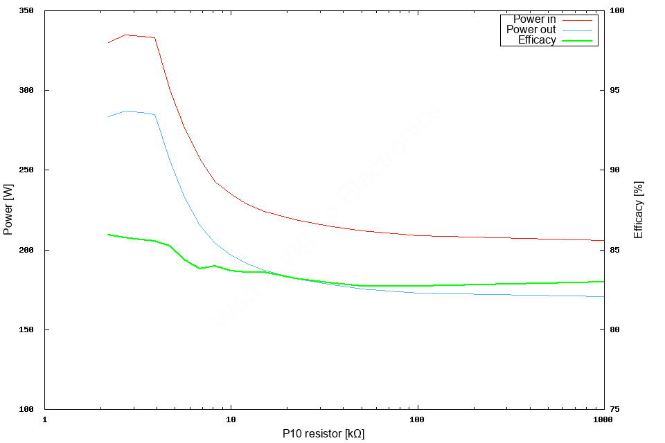
Furthermore, a quick graph on the resistor value: Above a certain load, let’s say 200W, the voltage drops significantly. Adding the correct resistor will fix this – I guess in real world scenarios, there would be a PWM signal from the rest of the PSU to tell the power source to up their game. This 11kΩ emulates this in my ~250W (all my lights plus a fixed 2Ω resistor across) load scenario. Efficacy is pleasantly high for such an old unit at a peak 86%, still increasing with higher load (69A at 12V = 828W, so this is only 33% load).
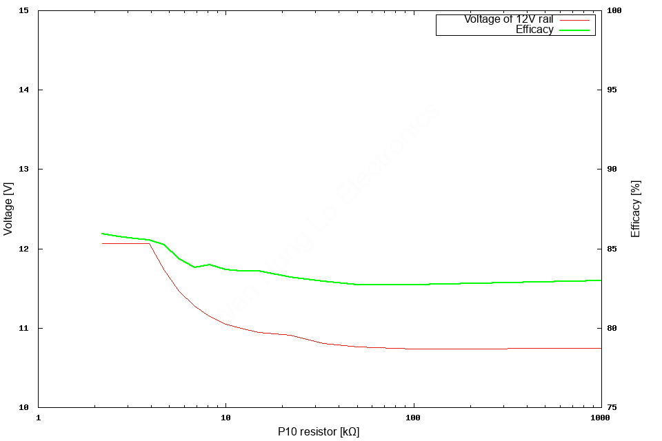
Here the significant drop in voltage can be seen. It must be noted that above a certain load figure and resistor value, especially when left completely open beyond 250W, visible flicker might occur. Adding capacitors will not help in this case, but adding the resistor will. Voltage at pin 10 must not rise above ~1.55V – otherwise it will flicker. So while I wouldn’t recommend shorting the thing as I do not know if that will harm the PSU, choose the “sense” resistor accordingly. I set mine to 11kΩ and it’s perfectly fine (both voltage and flicker), since I’m running a little lower in total power as in the shown dataset.
Files for download: Kicad project and original Gerbers.
Hi friend, I search a lot to find your post here.
I have 4 unit like this one and I’d love to use them as a power supply for my mining rigs.
So, i’d like to use them at max power. What do you recommend to do?
And if possible what are the pin the i need not “short” to make it turn on.
Wan, I continue my research and find a very good post that answer all my questions:
https://www.rcgroups.com/forums/showpost.php?p=20400391&postcount=1114
I cannot verify this right now, but if true, that’s valuable information. Thank you.
As for the mining rigs: I’d recommend roughly 80% load since efficiency will likely drop beyond that. GND connection needs to be commoned with the ATX power supply of the board, and 12V of course goes to the graphics cards. Do not supply one card from two power supplies, PCIe power connection included.
Good to know…thank you so much