
O’CELL 26650 LiFePO4 8S 3.3Ah battery pack with BMS (WHL #28)
Same thing again – but different manufacturer. That’s what you get when you clean up your new lab… ![]()
I know, might be boring to see another battery pack with almost identical specs (3.3Ah instead of 3.2Ah), but trust me, this is like night and day – or like quality China and Wan Hung Lo.
Of course these two batteries were purchased at the same time for the same thing, and they cost around the same as well. But (spoiler!): These two units work fine.
Top view:

Nice shrink wrap, proper label (shout out to O’CELL and their caring but not nagging sales people). So this is an IFM24-33E2 unit with 25.6V rated voltage and 3.3Ah / 84.48Wh capacity. Again, this is a lithium iron phosphate battery with lower voltage than traditional lithium cells, hence the 3.2V nominal and 3.65V (x8 = 29.2V) charging voltage. The leads are flimsy but we ordered a low current battery, hence there’s no need for big wires like in quadcopter 100A+ battery packs. They will do 3A just fine and the silicone insulator material is good quality. Very flexible, easy to tin, and you can replace them if you need different leads.
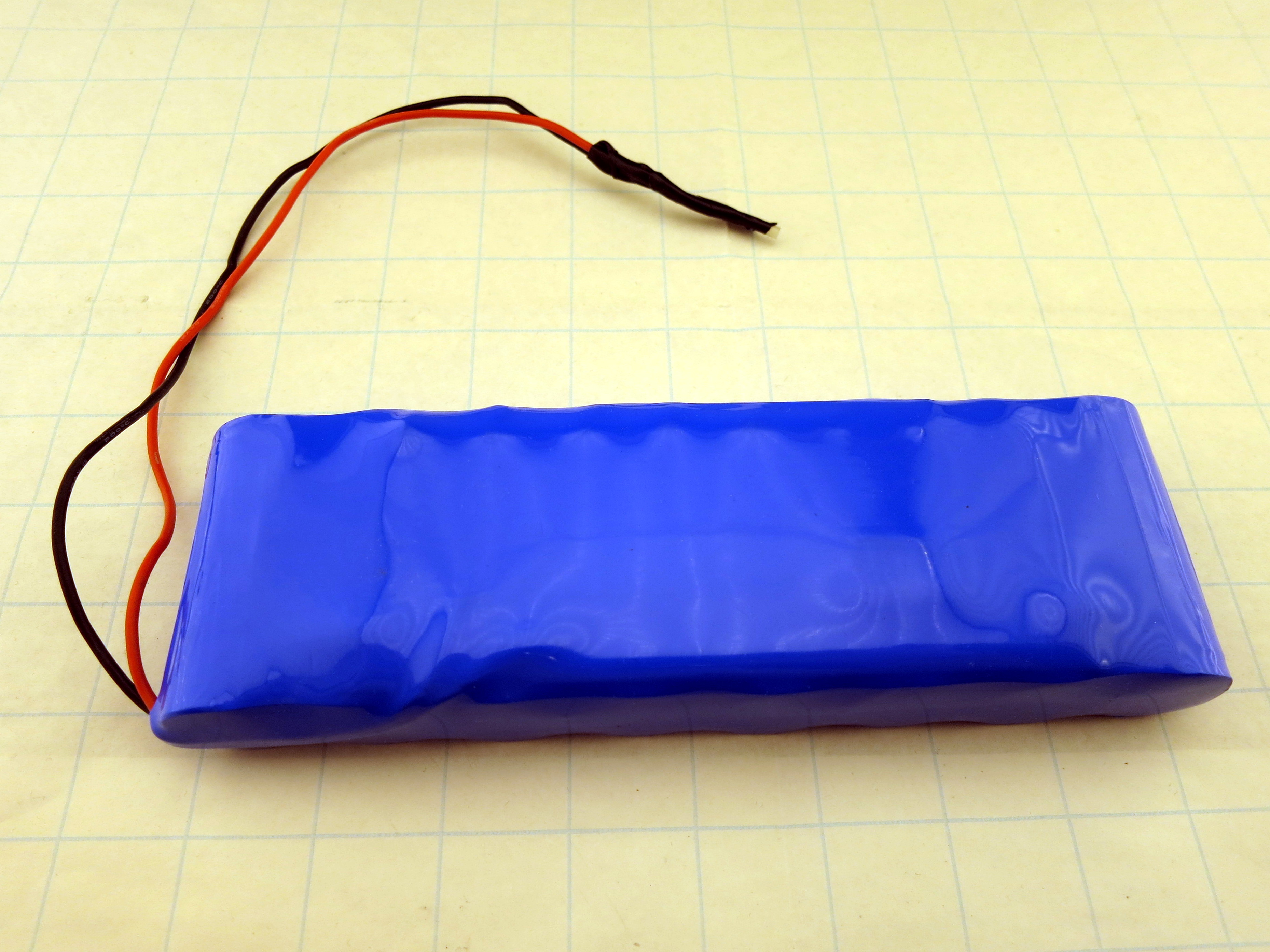
Backside is a tad boring, as usual.
Now the BMS is quite a bit larger, but the PCB isn’t really densely populated. Have a look:
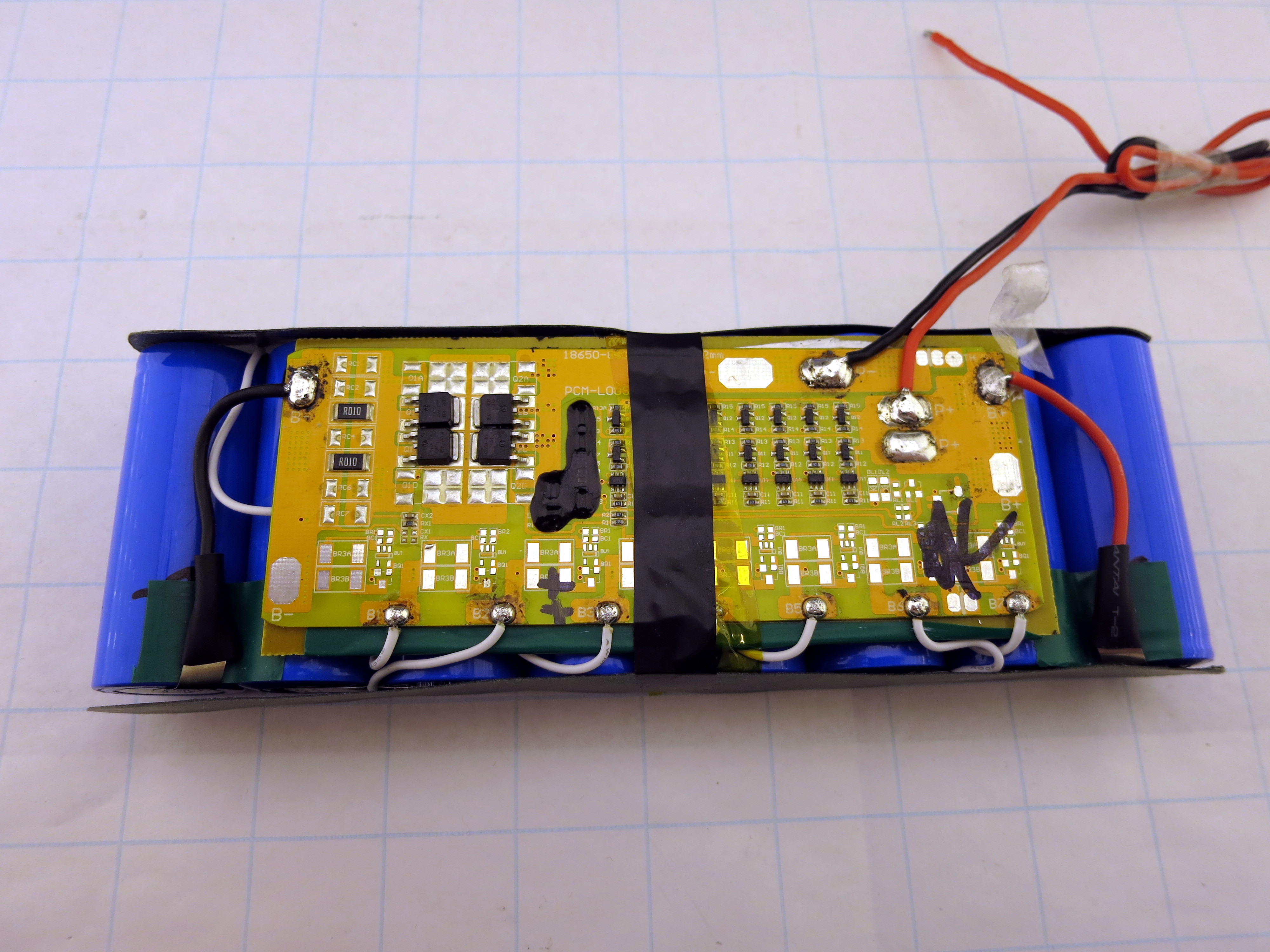
I marked the highest reading cell with the two pluses, the other marking is from the factory. The black stuff in the center (not the tape…) isn’t even marker or lacquer marker, it’s black epoxy. Not sure what to cover there – no microcontroller or the like here, just a few SOT23 trannies and some resistors. Unfortunately, the gunk isn’t brittle enough to scrape it away, it sticks very well and so you’ll erase the chip marking anyway.
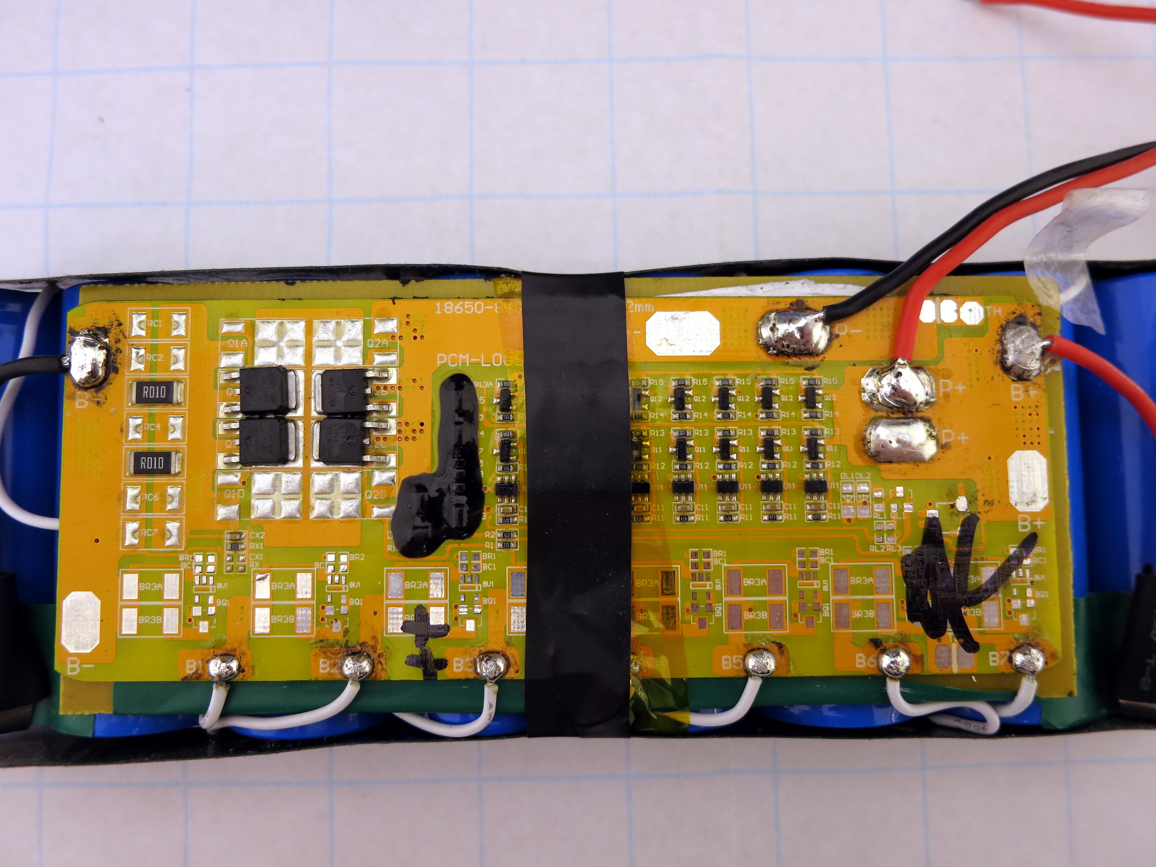
The four “K9209-40B” transistors in DPAK casing could very well be a NXP BUK9209-40B TrenchMOS logic level FETs, allowing for 40Vds, 75A Id (limited by the case), and 7.6 to 9 mΩ Rds at 5V gate voltage and 25A – that’s quite nice. They all share source and drain, and two adjacent ones also share the gate pin. Guess that’s okay when having such close thermal coupling and also a low overall current rating. Switching one amp at 29V each is a few milliwatts of dissipation, that’s alright…
Current sense resistance is 2x 10mΩ in parallel – that’s not much, but obviously does the job.
As you can see, the board isn’t fully populated, so I guess this is just the same PCB that is used in the more high-powered versions that are shown on OCell’s website. You can easily double up everything and connect additional wires to the board for better current handling. Also, like the other 26650 battery, the (+) pole of the last cell is directly connected to the outside (+) wire, yet they route the current over the board instead of tapping it off at the cell with large diameter wire and just use a thin sense wire like they do for any other cell.
As for the voltage checking, there are 8 identical circuits placed on the board. There’s more going on at the bottom near the individual soldering tabs (god, I did poke a lot of holes in there with my multimeter tips!), but all of that stuff isn’t populated. I guess one could do individual current measurements and also short single cells if they fail to preserve general function. There’s however no external connector to plug in a voltage checker or directly balance the cells. That’ll be a requirement for the next test candidates due to the experiences with the last 8S block…
The protection kicks in very late – I didn’t go below 2.4V on the weakest cell, but there was no clear cutoff (see below). I know the LiFePOs aren’t that susceptible to damage, but for a commercial BMS, I’d like to get some decent cutoff voltage. It’s not documented in the datasheet and I didn’t try to go all the way down – after all, this is a working battery pack and I’d like to keep it that way ![]()
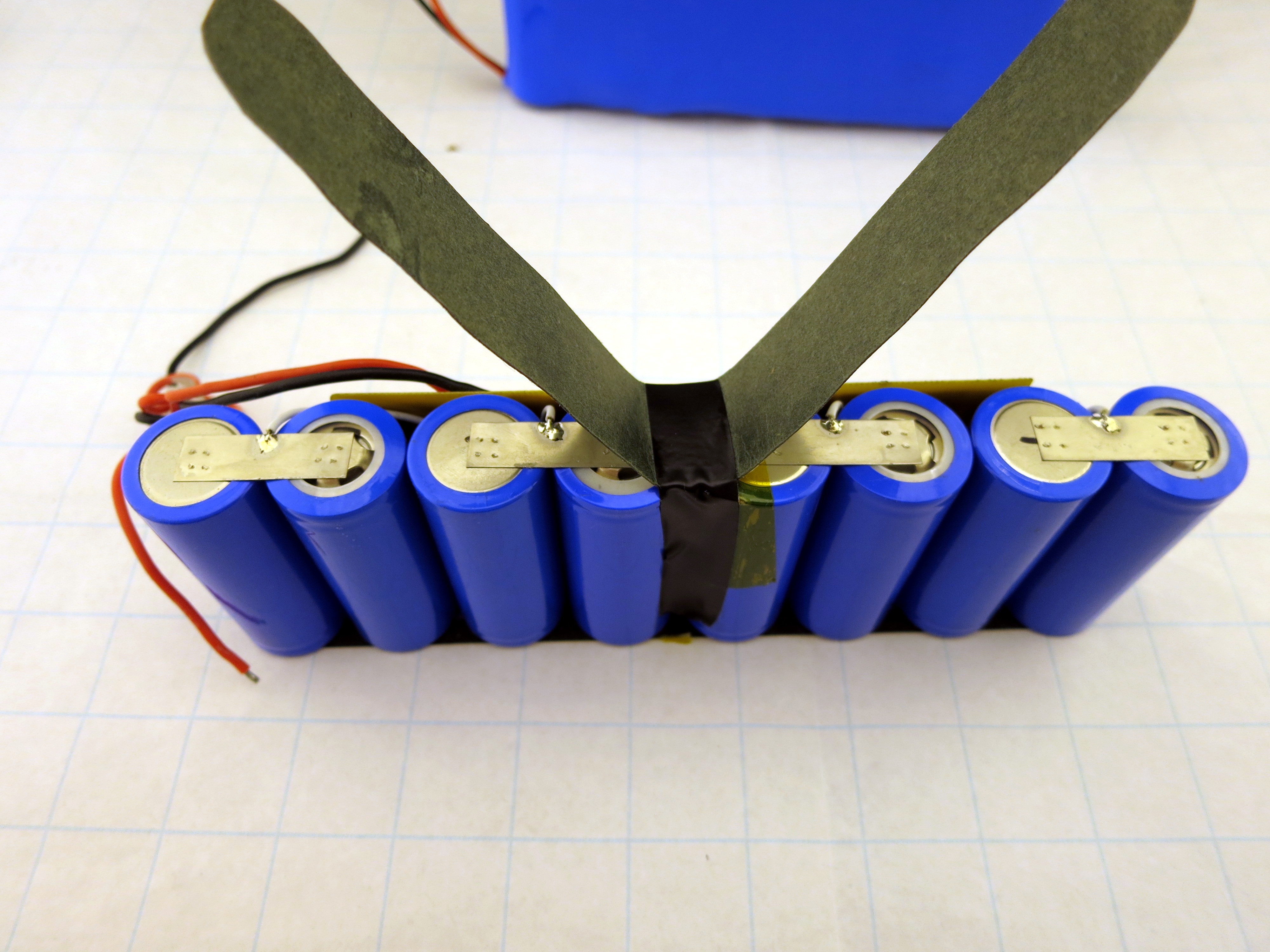
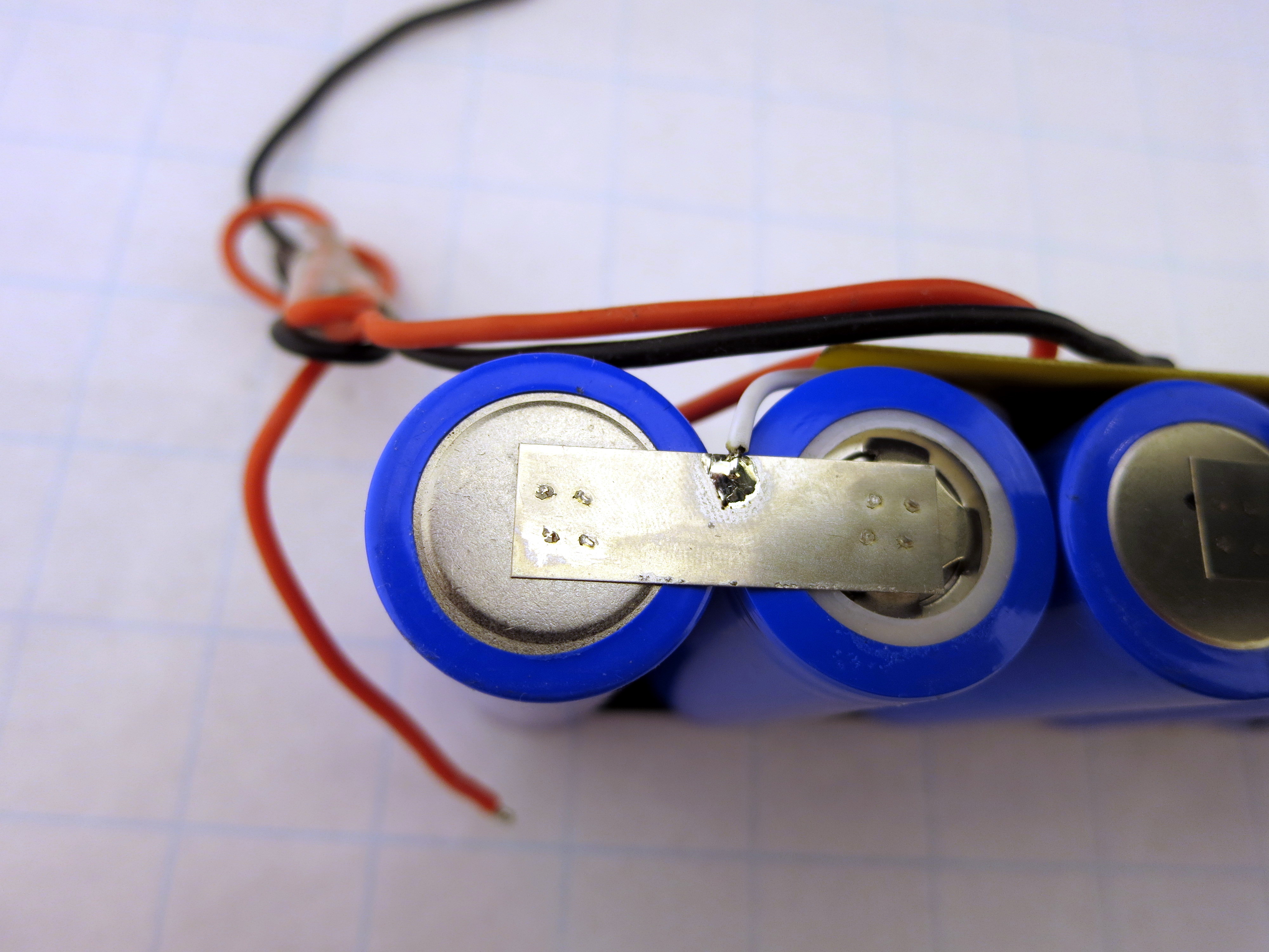
The cell voltage tapping looks okay, I liked the extra solder wedge a bit more. But the spot welding for the main current handling is much much nicer – 2×2 spots per cell, properly spaced, centered metal strips, done by a professional. Great!
Now the important part: Performance!
Once again, ~2A discharge from full charge down to ~2.6V of the weakest cell:

The first run stopped twice for some weird reason, and I wasn’t sure if it was the BMS that cut off the voltage or if my setup detected cell undervoltage (due to me touching the wires?) and stopped accordingly. But the second run went fine, so I guess it was my fault. Same goes for the steep drop in current of the second battery – ![]()
Readings were 3.2Ah/80Wh and 3.3Ah/83Wh for the first battery (the stripped one), as well as 3.2Ah/81Wh for the second one. So even if my setup reads high, it’s absolutely in the ballpark of the rated 3.3Ah and 84.5Wh. Perfect!
As for the rising current at the beginning of each measurement, I’ve finally checked that with an ATX power supply. Surprise, surprise, as I’ve noted down already, using the RDSon of the on/off MOSFET as a current shunt is a bad idea. Not a super bad one, but have a look at this graph:
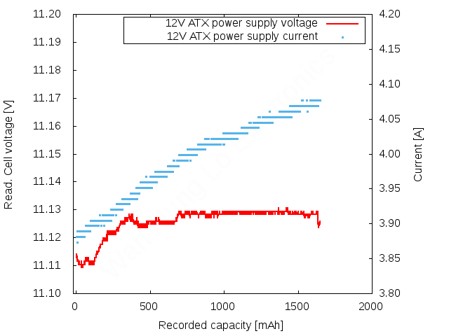
(different current and therefore axis labelling, to get to a similar power dissipation level with the available fixed voltage!)
The voltage is quite stable and voltage level is okay for a total of 3m of wiring. But the current reading goes up by 5%, while the UT203A clamp meter states a constant value. Most of that drift is caused by the MOSFET!
Hate to say that I have more data to support this claim in the next post – which will discuss another battery pack ![]() Sorry!
Sorry!
I need IFM24-33
Well, visit ocelltech.com then and get in contact. You might even let them know I sent you