
CITYSAX 160Ah LiFeYPO4 battery discharge and teardown (WHL #51)
Speaking of electric cars: A colleague recently bought a used electric car and (obviously!) contacted me in order to diagnose/troubleshoot it. Sadly he was able to sell it for a profit before we got it fully fixed, so no live data recordings, no power/torque graphs, no nothing to show here. But he left me a dead cell for which he got a replacement from the seller right away, as the traction battery had voltage dips under load that indicated (at least) one damaged cell.
If servicing individual battery cells sounds a bit strange for a modern electric car, that’s because we’re talking about a CITYSAX from a company that is conveniently named the same. Basically this is a professionally retrofitted 2nd gen Daewoo/Chevrolet/Pontiac/FSO Matiz (also known as Joy and Spark in some combinations, thanks, GM!), it was produced from 2009 to 2011 in small batches in Germany, and therefore this is an extremely rare production car. There are probably more McLaren F1 still alive than Citysax touring the streets.
The Citysax has a 83V battery system with 13kWh nominal capacity, consisting of 26 (I think) beefy LiFePO4 (LiFeYPO4, so heavy Yttrium doping) cells at 160Ah each, protected by two separate BMSes (trunk and frunk space differs in size). The motor offers 16kW (26kW peak) and 51Nm (96Nm peak), which allows for 130km/h top speed and 120km of range; curb weight is just shy of one ton. They claim 130 to 180 Wh/km energy consumption wall-to-wheel, which indicates a terribly inefficient charging system. At 35000€ a pop this was certainly an interesting thing for research in 2009, but nothing that would ever conquer mainstream. My decision to buy a Tesla hasn’t been affected by this at all, I promise ![]()
Now, for the single cell: I didn’t even take an overview picture, so here’s one with a nice watermark from a Chinese seller (very interesting logo…):

It does say “MADE BY THUNDER SKY” on the side and some Chinese characters on the other, but apparently these are called Winston cells, possibly WB-LYP160AHA in this case. The 160Ah model fits the outer size of my cell nicely and the capacity is required to achieve 160Ah/cell*3.2V nominal*26cells = 13.3kWh total.


The back and sides have nothing on them, the case is some jar-style plastic body that everything is put in, and the top is added like a lid and then sealed shut.

This one was marked as defective when I got it, which isn’t all that surprising given it had a noticeable bulge on the sides. Some people say that is normal for those cells, I don’t think so – that’ll not only damage neighboring cells if no proper spacing is used during installation, it also indicates that either there is A LOT of gas pressure inside or that the battery layers somehow got puffed up, which both doesn’t sound all that healthy for battery chemistry that claims 2k-5k recharge cycles.

The center cheesy logo thing hides a vent plug made from the very same yellow plastic. It is threaded big time and has an Allen key for removal, and when I did, it violently skipped the last few threads. Think of a bottle of champagne, shaken, not stirred…
At this point the cell was starting to smell, a very distinctive pure battery electrolyte type of smell. Not disgusting – but I’m not sure if all that healthy. I initially thought this battery consists of individual smaller cells put together and connected with large bus bars, and one of them has popped, oozing out its guts – well, nope, but that’ll show in a minute.
With some test cuts I figured out how thick the shell material was, in order to cut it open safely. Imagine shorting the entire stack at once by a well placed saw blade stroke ![]() Also, consider the pressure requirements to bulge that solid structure out by just a millimeter. Later, I stood on top of it and that hardly did anything – averaging 20kPa over the entire surface.
Also, consider the pressure requirements to bulge that solid structure out by just a millimeter. Later, I stood on top of it and that hardly did anything – averaging 20kPa over the entire surface.

Speaking of the bulge: There’s a video of this type of cell being abused twice, and overcharging (they did 4.2V, manufacturer says 4.0V, I’d not go much above 3.6V) does seem to generate a lot of gas inside. It also cannot escape as the venting mechanism is flawed, the plug would not pop out and the threading is sealing too well for large amounts of gas to escape. Hence…it ruptures when short-circuited in overcharged condition. After a very anti-climactic 13 minutes… (2:20 in the video)
Inhaling the fumes also makes you choose very interesting background music for that kind of video.
The inside looks like this:

There’s a whole bunch of cells crammed inside, each covering the entire area available. They are divided into two packs with approximately 50 pieces each. The contact tabs are lined with copper and aluminium on the outside, screwed to the massive contacts (40mm x 25mm base, M8) with two screws each, and those terminals protrude the front. Once they align, they are fastened, then the lid is sealed, and then the terminals are fastened to the upper side of the lid. That way, there should be virtually no movement inside once the cell leaves the factory.

At this stage it still wasn’t obvious to me that these are the naked cells, I still thought these were individual ones that could be separated once removed from the case. I did a full charge-discharge cycle at 10A at this point, down to 2.2V under load conditions. Manufacturer recommends 2.5V – that was still present open circuit; I also never touched the recommended discharging current of 0.5C = 80A and certainly not max continuous discharge at 3C = 480A. Peak discharge is rated 20C = 3200A at 1:12 duty cycle…
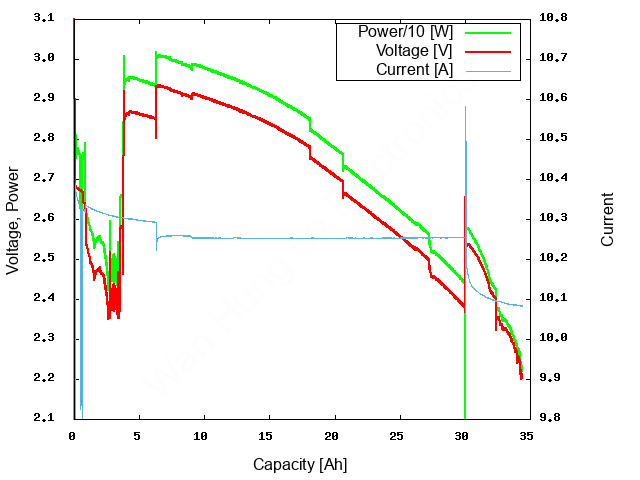
This data is heavily processed as I’m currently having a hard time with false readings on the electronic load that’s in migration to the ESP32 platform + large display. I’ve filtered these and stitched two discharging sessions together – I’m glad if I hit 10% accuracy on these numbers. Hard voltage jumps are caused by touching the connectors, that crap at the beginning – who knows. The current levelling at the end is not caused by the load being capped at minimum resistance, even though we’re talking about 0.22Ω (2.2V, 10A) here. 34.4Ah and 91.8Wh is what I got after all corrections. Take it with double the number of grains of salt compared to my usual results.

Having the fully upgraded HP6644A at my disposal was a big help here, as charging “160Ah”@3.6Vmax at 1A max over a wonky 4mm connector with cheapo voltmeters attached would have been quite a journey. This was also sort of a burn-in test of all components involved – fan, caps, front panel wiring, as described in both articles.
Well, step forward and I cracked open more of the shell, resulting in large amounts of yellow dust that goes everywhere. That stuff is really tough. Here’s the freed cell, and, oh shit – this is bare ass cells directly sandwiched on top of each other.

Count them if you want to…

See the geometric distortion of the topmost cell, this certainly has had a negative effect on capacity and especially on the internal resistance of the entire assembly – hence the “Ri” marking from the technician that classified this one as defective.

The copper sheets (negative terminal) are extremely brittle, comparable to let’s say chocolate of similar thickness. Not sure if that’s from the cells being dried up, some oxidation process, or the cells being heavily discharged. There’s no way to separate the copper from the applied lithium paste. The aluminium ones are much more flexible and thicker, very much like aluminium tape. These could be separated in a messy process. The separator foils are surprisingly thick; I once made my own lithium cell at the Fraunhofer institute of silicate research (ISC) during some interdisciplinary chemistry lessons, and we put in much more of the black lithium goop in comparison to the thickness of the foils ![]() Good times…
Good times…

So here’s the extracted block of cells, happily sitting at 3.1V open circuit voltage in fresh air.

It’s dead and that’s only a phantom voltage you say? Well, not quite. I ran it at 1A for an entire day, starting at 3V. I then switched to a higher load, as those cheapo Pollin leads have about 1Ω of resistance. I let it sit for another day at 2.5A (declining)

And then I clamped it down entirely. Sparkly feels on connecting both terminals. Each half was still capable of 20 amps for brief moments of time. Down to 100s of millivolts, but the punch was still there.
As I did unlock a CAT S60 for work that was about to be thrown away due to the crippled second SIM slot (thanks T-Mobile! Bastards…), I also have photographic proof. Yes, the meter is reading a combined 20A in here, and when standing on it, compressing the layers, that could jump up quite a bit.


Current at the end of my week long torture was something like 0.4A at an open circuit voltage of 250mV, still producing some 10A when disconnected for a short time and then shorted again (or stepped upon…). Beefy on its own, not much considering its size (and intended purpose).
Interestingly the two different packs also show up on the IR photo, the upper one being weaker due to more layers missing, destroyed, crumbled. The leads are clearly closer to room temperature, still we’re only talking about 11K above ambient, so no fire hazard here at this stage. Doing that with the charged battery…well, see above.

I ended up taping it back together in the shell, putting on a transparent cover over the contacts for the recycling guy to not be afraid of the insides, and giving it to the local recycling depot.
Done. Don’t expect me to do this on a Tesla battery, there are truly mad people on YouTube that already did. Hint: Shorting those is a friggen BAD idea ![]()